For customers outside Calgary, please call toll free
+1 (833) 290-6300 For customers outside Calgary, please call toll free
+1 (833) 290-6300
+1 (833) 290-6300 For customers outside Calgary, please call toll free
+1 (833) 290-6300


One of the most cost effective methods of removing accumulated liquids from the tubing and annulus of a high Gas/Liquid Ratio (GLR) natural gas or oil well, plunger lift has become increasing popular throughout North America since the 1980s.
As a well ages, production naturally declines as reservoir pressure decreases, and liquid loading becomes a problem when the well’s energy is no longer sufficient to remove liquids on its own. At this point, intervention is required to keep the well producing at an economical rate.
Plunger lift has been proven to dramatically increase production, and is a low cost, low maintenance solution to liquid loading bearing very minimal environmental impact.
Plunger Lift System
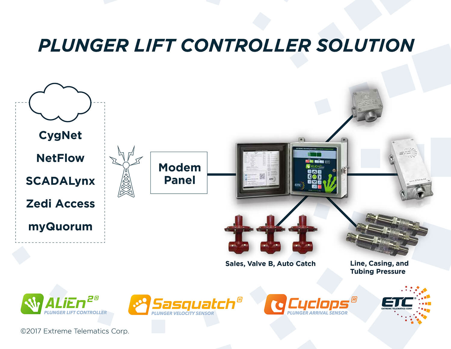
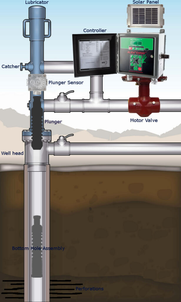
Typical system components include a controller, plunger arrival sensor or plunger velocity sensor, plunger, lubricator, motor valve, and bottom hole assembly.
The controller is the “brains” of the system – It tells the motor valve when to open or close, and monitors the plunger arrival and pressure sensors. There are many controllers available in the form of standalone plunger lift controllers or remote terminal units (RTUs), each presenting their own set of features and benefits. Basic controllers serve to simply run the system while more complex controllers are able to automatically optimize production and allow for remote monitoring and control as part of a SCADA system.
The plunger arrival sensor is a small but critical component of the plunger lift system. Its purpose is simple; to notify the controller of a plunger’s arrival at surface. A plunger velocity sensor replaces the arrival sensor to signal arrivals and record a plunger’s velocity, giving the ability to calculate kinetic energy to comply with the API 11 PL standard kinetic energy rating on a lubricator.
The plunger’s primary function is to act as an interface between gas and liquids inside the tubing or casing; carrying a column of fluid above it to the surface of a well. Plungers come in a variety of types to meet the needs of a particular well.
The lubricator extends the wellhead to receive the plunger at surface, and contains a high impact spring to absorb the impact of the plunger as it arrives. Several different styles of lubricators are available, featuring single or dual ports and threaded or flanged connections. Lubricators made from different materials are also available to account for different types of gas being produced (sour or sweet), and adapt to environmental and safety conditions at the well site. Some lubricators feature an auto catch to allow the plunger to be held at surface after it has arrived to allow the well to flow more freely.
The motor valve is installed at the wellhead to shut in or open up the well to allow gas to flow to the sales/production line.
The bottom hole assembly is installed just above the perforations deep within the well to absorb the impact of the plunger, ensure the plunger stops above the perforations so the gas comes in below the plunger, and prevent damage to the seating nipple and tubing.
ETC Plunger Lift Solution Brochure
This form of artificial lift utilizes a natural gas well’s own energy to run a plunger up and down the wellbore. In its simplest form, a plunger cycle begins when an electronic controller located at the wellhead actuates a motor valve to shut in the well temporarily, cutting off gas flow and allowing the plunger to fall from the lubricator down the well inside the well’s tubing or casing.
The plunger falls through accumulated fluids and comes to rest on the bottom hole assembly. After a set time, when the plunger is assumed to be at bottom, the controller signals the valve to open again, and the pressure in the well below forces the plunger back up the wellbore carrying the column of fluid.
As the plunger returns to the lubricator, fluids are forced out through the sales line, or in some cases, out to a holding tank. At this point, the arrival of the plunger is detected and the controller moves into the next phase of the cycle, commonly referred to as the “afterflow” or “sales” portion of the cycle. This portion of the cycle is carried out for a period of time determined and set by the operator, after which the cycle beings again with the closing of the valve.
Modern controllers, like the ALiEn2, contain optimization algorithms that track the plunger’s arrivals and make automatic adjustments to close and afterflow times to maximize production.
The goal is to minimize the amount of close time (not producing = not making money!!) and maximize afterflow time while avoiding plunger “fast trips” which are dangerous and cause damage to surface equipment. There are many system configurations available through the use of different plungers, pressure sensors, surface equipment, and time or pressure based algorithms existing in modern controllers.
The ALiEn2 plunger controller replaced a competitive controller on a plunger lift well that was not meeting production expectations. Production was doubled within 12 days and the well has continued producing at the higher rate since.
The Cyclops sensor was installed on wells that were frequently missing plunger arrivals, leading to 100% reliable detection of the plunger.