For customers outside Calgary, please call toll free
+1 (833) 290-6300 For customers outside Calgary, please call toll free
+1 (833) 290-6300
+1 (833) 290-6300 For customers outside Calgary, please call toll free
+1 (833) 290-6300
December 16, 2015

Extreme Telematics has just developed the first commercially available plunger velocity sensor, Sasquatch. Getting to this point took a lot of testing, and we first had to figure out how to consistently replicate how a plunger moves in a lubricator.
As with any company involved in product development or engineering, verification of a product is just as important as product design. In order to design a device to measure velocity, we had to design a way to control the speed of a plunger.
We broke down the problem into two parts:

Test set up using gravity to simulate plunger arrival
The first plunger velocity test system consisted of an inverted lubricator and piping. Plungers were dropped and their waveforms were measured. Using the weight of a plunger and controlling the height at which it was dropped from allowed us to theoretically calculate velocity. The drawback to this approach is the maximum speed achieved was limited by the height the plunger is dropped from. In an office environment the height the plunger can be dropped from is also limited to a few feet.
After revisiting the drawing board, a new test system was designed. Motors and pulleys were chosen to accelerate the plunger. With a powerful motor and an appropriate flywheel we could accelerate the plunger to speeds of 700 – 800 ft / min (200 to 300 m/min). We then focused on measuring the plunger’s velocity. Using pairs of infrared beam sensors, similar to an elevator door, the speed of the plunger could be measured manually using an oscilloscope. Each pair of sensors will detect the plunger breaking the infrared beam as it moves. By mounting a lubricator with spring to the pipe, the effects of the plunger slowing down as it strikes the spring could also be measured.
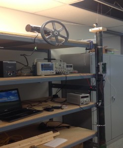
Motor driven test setup

Motor driven test setup
Engineers are never satisfied with just solving a problem and always look for ways to improve on a solution. This is true for the plunger test system. The forces involved in accelerating and stopping a plunger can generate significant wear and tear on whatever the piping and lubricator are mounted to. Mechanical failure can lead to downtime and we had to frequently repair the test system. We also found that the infrared beam sensors can sometimes detect the cable pulling the plunger instead of the plunger itself. Lastly, measuring velocity manually can be imprecise and prone to human error.
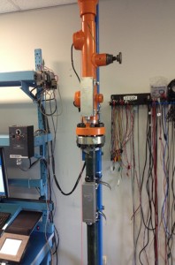
Fully automated plunger arrival test setup
To improve the mechanical stability, a new stand was designed to mount the lubricator, pipe and motor. Industrial capacitive sensors (using technology similar to how the touch detection on your smartphone works) would be immune to any cables or ropes pulling the plunger. Mounting a pair of these sensors flush to the inner wall of the lubricator provided better accuracy than the infrared beam sensors. With a programmable motor controller, a computer can control the speed of the motor and measure the infrared or capacitive sensors. The controller can also be programmed to simulate some effects, such as a bouncing plunger.
As you can see, the path to creating a rugged, reliable and safe product includes a lot of steps and often faces many challenges along the way. Be sure to check out the results from our Sasquatch field trials, where we learned that instantaneous surface velocity can be notably different from average velocity, and sometimes dangerously so.


